
glossary
Scribe
Scribe (scribe line, scribe street) is the street between copies on the finished disk, left empty enough that a saw or laser can cut without killing the circuit.
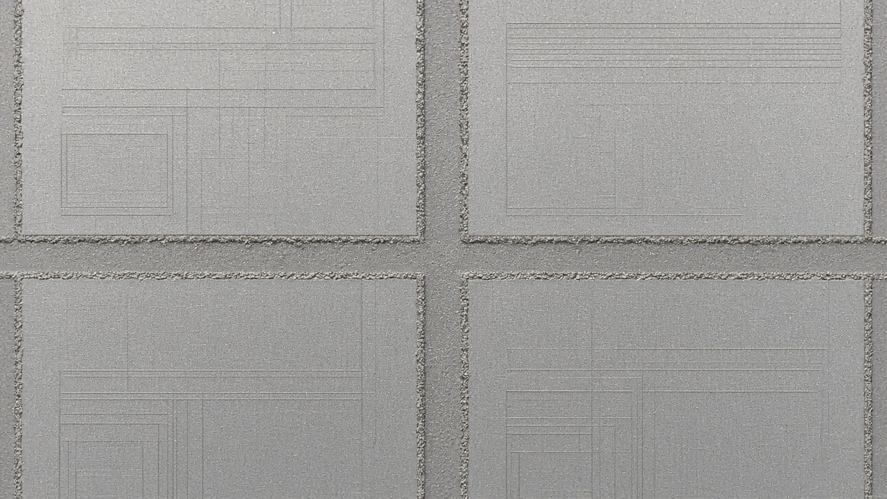
Empty lanes between the copies. A saw travels in those lanes.
The street is not wasted white space to steal for a last-minute capacitor. It holds process monitors, alignment marks, and a keep-away for the blade. A typical street might be 80 micrometers wide. Narrow it without asking the foundry and the saw walks into pads. On a wafer map the street is a grid of gutters around each die. In the top cell a frame may be drawn, or a margin left, as the assembly notes require. Some shops put test keys in the scribe. Those keys vanish when the wafer is diced.
The disk being cut is the wafer. The plate that printed the fields is a reticle. The useful drawing stops at the die edge, and then the street begins. Scribe width is a foundry number: 60, 80, or 120 micrometers, depending on the saw, the laser, and the test keys. Those keys are process monitors. They are not your IP. Do not route a secret net through the street. After dicing, only the die remains, plus whatever the package sees on the edge.
Real pin pads drawn in the scribe because there was room become dust after sawing. Put the pads inside the die, and keep the street as the foundry drew it in the PDK.
The plate, the disk, and the copies are covered in what a photomask is, what is a layout, and cells and instances.