
glossary
OPC
OPC (optical proximity correction) is the deliberate addition of extra jogs and serifs to a plate drawing so the printed result on the disk looks like the shape that was meant.
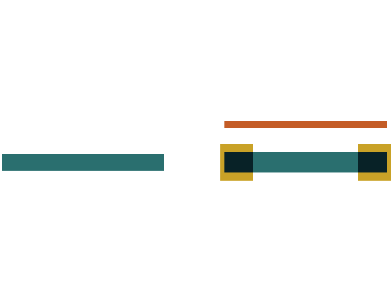
The left line is plain. The right line has wide ears at the ends and a thin bar running beside it.
Light is messy. A 0.1 micrometer line does not print as the rectangle that was drawn. Neighbors steal light. Corners pull back. OPC adds hammerheads, line-end extensions, and assistant features on the photomask so the wafer image is closer to the design. A designer may never draw those shapes by hand. A foundry deck does. A “mask view” is full of dog-bone ends and tiny assist bars that are not in the designer view. A 70 nanometer gate might grow ears on the plate.
OPC is one reason GDSII files explode in size. Fracture then slices those jogs for the mask writer. A stepper and the illumination recipe are part of the same story. The correction is a letter to the optics. It is not the circuit. Change the design layer, then regenerate the correction. Editing the OPC shapes as if they were the devices writes the wrong letter.
Designer-level rules already bake in some optical pain: minimum width, end-of-line, and forbidden pitches. OPC is the next shift, usually at the foundry. A “recommended” pitch in the PDK can print cleaner after OPC than a slightly denser pitch. Extra jogs placed on a design layer to imitate OPC will fight the real correction later. The plate that receives the corrected shapes is what a photomask is, and the camera that shrinks them is steppers and why size matters. The widths you were already required to draw are the subject of design rules and DRC.