
glossary
Microfluidic
Microfluidic layout is the drawing of tiny channels and chambers for liquid or gas, as outlines a shop will cut, mold, or laminate.
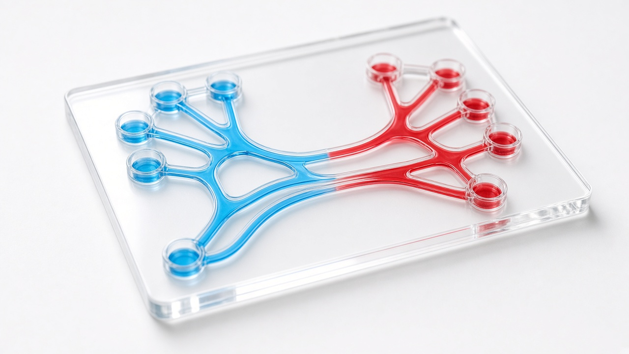
Channels in a clear plate. Two liquids meet in the middle.
The file looks like a chip drawing and behaves like plumbing. A channel 50 micrometers wide and 20 micrometers deep is a pipe. A sharp inside corner traps bubbles. A 2 millimeter chamber needs posts so the roof does not sag. Connections to the outside world are ports, not pin names from a digital library. On screen the channels are long serpentine path objects, or polygons with rounded corners, often exported toward DXF for a mill or a soft-lithography mask.
The process cousin is MEMS: the same 2-D habit, a different recipe. An optical cousin is a waveguide, which guides light instead of liquid. Width and spacing still matter, now for flow and bonding, not only for shorts. A channel is not a wire that can Manhattan-stair at no cost. Fluid notices every corner. Draw the path the liquid is meant to take.
Bonding and lids are part of the drawing. A 40 micrometer-wide channel that looks open in 2-D can pinch when a PDMS lid sags. Alignment marks belong on the drawing for multilayer soft lithography, and ports sit on a 1.5 millimeter pitch for tubing. Boolean tools still help: punch via holes between channel layers the same way a chip punches a via. A channel that carries liquid instead of current is channels, not wires. The recipe that decides whether that channel is open is MEMS is layout plus a recipe. The sheets the channel is drawn on are still what is a layout.