
Shapes · Files
Polygons in a layout: vertices, holes, and why a box is not enough
A layout polygon is a closed list of vertices on one layer: how GDSII and OASIS store it, vertex order and area, holes as cut lines, broken polygons, vertex limits, and how to check them in LayoutEditor.
Last edited: October 26, 2026

A polygon in a chip or MEMS layout is a closed list of vertices on one layer, joined by straight edges, with the enclosed area filled. It is the general shape type of the layout formats: a rectangle, an L, a comb, a pad with a hole, and an approximated circle are all stored as one vertex list. GDSII calls the record a BOUNDARY, OASIS calls it a POLYGON, and LayoutEditor calls it a polygon.
The image at the top shows four metal 1 (met1) polygons as LayoutEditor holds them, with a red square on every stored vertex. The comb at the bottom left is one polygon with 12 vertices, not a bar plus three teeth. The L at the bottom right has 6 vertices. The octagon at the top right has 8 vertices and four 45° edges. The pad at the top left has 12 vertices and a square hole: the thin horizontal line on its left side is the cut line that connects the outer contour to the hole, explained below.
How GDSII and OASIS store a polygon
GDSII writes a polygon as a sequence of records. The record codes below are from the Calma Stream format description (Holwerda transcription); coordinates are 4-byte signed integers in database units.
| Record | Code (hex) | Content |
|---|---|---|
| BOUNDARY | 0800 | start of a polygon element |
| LAYER | 0D02 | layer number, 0–255 in the original specification |
| DATATYPE | 0E02 | datatype number, 0–255 in the original specification |
| XY | 1003 | vertex list; the first coordinate is repeated as the last |
| ENDEL | 1100 | end of the element |
The specification text sets a boundary to at least 4 and at most 200 coordinates, and requires that the first and last coordinates coincide. A triangle therefore takes 4 XY pairs and the L above takes 7. A rectangle can also be written as a BOX element, which has exactly five coordinates. Each element stands alone: GDSII has no record that makes one boundary a hole in another.
OASIS (SEMI P39) stores a polygon in a POLYGON record, code 21, with an initial vertex and a point list of displacements. The draft specification (SEMI document 3626, 2003) defines six point-list types:
| Type | Stored per vertex | Valid for |
|---|---|---|
| 0 | one signed length, horizontal first, then alternating | Manhattan polygons |
| 1 | one signed length, vertical first, then alternating | Manhattan polygons |
| 2 | one length with a direction (east, north, west, south) | Manhattan polygons |
| 3 | one length with one of eight directions | horizontal, vertical, 45° edges |
| 4 | an x and y displacement | any angle |
| 5 | the change of the previous displacement | any angle |
The closing edge is never stored, because it is implied by the last vertex and the start point. For types 0 and 1 the last two displacements are implied as well. The draft treats a polygon with fewer than three vertices as a fatal error. Choosing the cheapest point-list type for each shape is one of the reasons an OASIS file is smaller than the same data in GDSII; see OASIS and GDSII.
Vertex order and area
GDSII assigns no meaning to the direction of the vertex list. The Artwork Conversion description of the format states that clockwise and counterclockwise lists are equivalent. Software that offsets edges (sizing, bias, DRC width checks) needs to know which side of each edge is inside, so most tools normalize the order. The LayoutEditor documentation states that it sorts polygon points counterclockwise. The test for this page confirms it: an L written clockwise into a GDS file is reported counterclockwise after loading, also with both polygon clean-up options switched off.
The signed area of a simple polygon follows from its vertex list with the shoelace formula: A = ½ Σ (xᵢ·yᵢ₊₁ − xᵢ₊₁·yᵢ), summed over all edges. A positive result means counterclockwise order. For the L with vertices (0, 0), (3, 0), (3, 1), (1, 1), (1, 3), (0, 3) in µm, the sum gives 5.000 µm², which equals a 3 × 1 µm foot plus a 1 × 2 µm stem. The formula is only valid for polygons whose edges do not cross; for a crossing contour, parts of the area cancel.
Polygon, box, or path
A box is the special case of four axis-parallel corners, stored as two corners in LayoutEditor and as a BOX or a five-point BOUNDARY in GDSII. A path is a centerline with a width; its outline is computed from the centerline, the width, and the end type. Operations that cannot keep those forms produce polygons: a rotation by an angle other than a multiple of 90°, a chamfer, a boolean operation, or a merge. LayoutEditor has two save options for receivers that accept only polygons: gdsBoxToPolygon and gdsPathToPolygon write boxes and paths as BOUNDARY records.
Shapes that touch are not one polygon
The comb in the image at the top can also be drawn as four rectangles: a 6 × 1 µm bar and three 1 × 3 µm teeth that overlap the bar. On screen both versions look the same. In the file they differ:
| Version | Elements | Vertices | Sum of element areas | Covered area |
|---|---|---|---|---|
| one polygon | 1 | 12 | 12.000 µm² | 12.000 µm² |
| bar plus three teeth | 4 | 16 | 15.000 µm² | 12.000 µm² |
The four-rectangle version counts the three overlaps twice. Tools that sum element areas, such as a quick density estimate, report the larger number. A merge computes the union: in the test, LayoutEditor's merge of the four rectangles returned one polygon with 12 vertices and 12.000 µm². Whether to keep separate shapes or merge them is covered in merging polygons and overlapping is not merging.
Holes without a hole record
Neither GDSII nor OASIS has a separate record for a hole. A pad with a window is stored as one contour that runs around the outside, follows a cut line to the hole, runs around the hole in the opposite direction, and returns along the same cut line. The Artwork description calls this a self-touching, re-entrant, or keyhole polygon and states that it is allowed in GDSII, whereas a contour that crosses itself is not.
The pad in the image at the top is such a polygon. Its outer contour is 4 × 4 µm, its hole is 2 × 2 µm, and the cut line runs horizontally from the left edge to the hole. The stored list has 12 vertices, because the two ends of the cut line appear twice, and the area is 16 − 4 = 12 µm². The LayoutEditor documentation recommends horizontal or vertical cut lines, which keep later polygon operations simple. How holes behave in merges and booleans, and why a hole drawn as a second shape on top is not a hole, is the subject of holes in polygons.
Broken polygons
A vertex list can describe geometry that readers interpret differently. The OASIS draft states that the interpretation of self-intersecting polygons, re-entrant polygons, and polygons with zero-area regions is application-dependent. Mask data preparation treats several of these as errors.
| Defect | Example | Status | What LayoutEditor does on load |
|---|---|---|---|
| self-intersection | bowtie: four vertices whose edges cross | GDSII: "illegal" per Artwork; signed area of a symmetric bowtie is 0 | rewritten as two triangles that touch at the crossing point |
| zero-width spur | an edge that runs out and back on itself | legal coordinates, no area | spur removed |
| duplicate vertex | the same point twice in a row | legal, redundant | point removed |
| unclosed boundary | last XY differs from the first | violates the GDSII rule above | written back closed |
The repairs in the right column depend on two setup options, defaultPolygonFixSelfintersectingPolygons and defaultPolygonRemoveNotNeededPoints, which are on in the tested installation. With both options off, the bowtie keeps its four vertices and a signed area of 0, and the spur keeps all seven vertices. The duplicate vertex is removed in both cases. A repaired bowtie is still two triangles that meet in one point, which a spacing rule can flag.
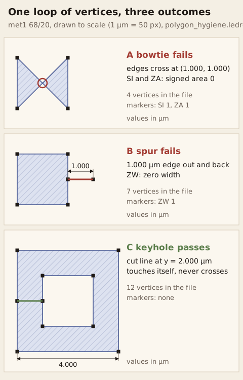
The diagram shows three polygons at 1 µm = 50 px, with every vertex from the file as a black square. A is a bowtie whose four vertices are the corners of a square; its edges cross at (1.000, 1.000) µm, circled. B is a square of the same size with a 1.000 µm spur, drawn as the red line. C is a keyhole pad; the green line is its cut line, where the contour touches itself without crossing. The same coordinates were written to a GDS file without any editor clean-up and checked with the deck below: LayoutEditor reported a self-intersection and a zero-area marker for A, a zero-width marker for B, and nothing for C.
The check runs on the file as exported, because the .ledrc engine reads the raw coordinates. The deck uses the shape checks from the LayoutEditor .ledrc reference and the SKY130 grid rule x.1b:
units 1e-6
layer m1 = input(68, 20)
check "SI"   "self-intersecting polygon"           : self_intersecting(m1)
check "ZW"   "zero-width out-and-back edge"        : zero_width(m1)
check "SP"   "spike, interior angle < 1 deg"       : spikes(m1, 1)
check "ZA"   "zero-area shape"                     : area(m1) < 0.000001 um2
check "x.1b" "vertex off the 0.005 um grid"        : ongrid(m1) != 0.005 um
layout --drc polygon_hygiene.ledrc polygon_cases.gds --outdir=outThe test file polygon_cases.gds holds nine cases on met1 at a pitch of 10 µm: the L, the same L clockwise, the comb as one polygon, the comb as four rectangles, the keyhole pad, the bowtie at x = 50 µm, the spur at x = 60 µm, a duplicate vertex, and a rectangle whose right edge sits at x = 81.002 µm. The report lists five markers; the six clean cases produce none:
SI  self-intersecting polygon   error   50000,0 51000,0 | 50000,1000 51000,1000 0
ZW  zero-width out-and-back edge    error   60000,0 61000,0 | 60000,1000 61000,1000 0
ZA  zero-area shape error   50000,0 51000,0 | 50000,1000 51000,1000 0
x.1b    vertex off the 0.005 um grid    error   81002,0 81002,0 | 81002,0 81002,0   0
x.1b    vertex off the 0.005 um grid    error   81002,1000 81002,1000 | 81002,1000 81002,1000   0
Precheck tools differ in coverage. According to the source of the open ChipFoundry precheck (cf-precheck v1.3.7), its default run has no general self-intersection check; a symmetric bowtie fails only its zero-area check, because the two lobes cancel. A hygiene deck of your own covers the cases above independently of the receiver.
Angles and the vertex grid
Each edge direction and each vertex coordinate is subject to process rules. In the SkyWater SKY130 periphery rules, x.2 allows only multiples of 90° on diffusion, tap, poly, li1 in the periphery, licon1, mcon, and the via layers, and x.3a allows multiples of 45° on the other layers. Rule x.1b requires every vertex to lie on a 0.005 µm grid; the case at x = 81.002 µm above violates it at both vertices of its right edge. An octagon such as the one in the image at the top meets x.3a and x.1b on met1 only if its diagonal edges run at exactly 45° and all eight vertices are on the grid. Angle classes and their cost are compared in Manhattan versus all-angle; grid snapping is covered in snapping and off-grid.
How many vertices a polygon may have
The GDSII limit of 200 coordinates dates from the original specification. The record header stores the record length in 2 bytes, so one XY record holds at most 65,535 − 4 bytes, or 8,191 vertex pairs of 8 bytes; the Artwork description recommends 8,191 as the reader maximum and a configurable writer limit, because receivers differ. LayoutEditor's GDSII options follow this: the setting gdsMaxPoints defaults to 8191, a polygon with more vertices is split into several polygons on save, and gdsMultiXYRecord writes one polygon across several XY records instead, an extension that is not part of the GDSII standard.

The second image shows the result of a lower limit. A 300-vertex polygon approximating a circle of 20 µm radius was saved with gdsMaxPoints = 200 and reopened. The file holds two BOUNDARY records of 152 XY pairs each; the seam across the middle is the shared edge of the two halves. With the default limit, the same polygon is one BOUNDARY with 301 XY pairs. The split keeps the covered area, but a downstream tool that does not merge the halves treats them as two shapes.
Each vertex also costs time downstream. Mask writers with variable-shaped beams expose rectangles and 45° triangles, so the fracture step splits every polygon into such shots; a curve approximated with many short edges produces many small shots. How the number of sides of a circle is chosen is covered in circles and curves; shot counts per shape in e-beam direct write vs. mask writing.
Polygons in LayoutEditor
In a LayoutScript program, cell.addPolygon(points, layer) adds a polygon from a pointArray; the documentation states that the last point is connected back to the first. In the test, a polygon created from 6 vertices was saved as a BOUNDARY with 7 XY pairs, the first equal to the last. The script below reports every polygon on one layer as LayoutEditor holds it after loading: start column, vertex count without the closing point, area, and orientation.
import sys
from LayoutScript import *

gds, layer = sys.argv[1], int(sys.argv[2])
d = project.newLayout().drawing        # 1 dbu = 1 nm
d.openFile(gds)
cell = d.findTopCell()

def signed_area(pts):                  # nm2
    n = len(pts)
    return sum(pts[i][0] * pts[(i + 1) % n][1] - pts[(i + 1) % n][0] * pts[i][1]
               for i in range(n)) / 2

rows = []
e = cell.firstElement
while e is not None:
    s = e.thisElement
    if s is not None and s.layerNum == layer and s.isPolygon():
        pa = s.getPoints()
        pts = [(pa.point(i).x(), pa.point(i).y()) for i in range(pa.size())]
        if pts[0] == pts[-1]:
            pts = pts[:-1]             # the closing point repeats the first vertex
        rows.append((min(x for x, y in pts), len(pts), signed_area(pts)))
    e = e.nextElement
for x, n, a in sorted(rows):
    turn = "counterclockwise" if a > 0 else ("clockwise" if a < 0 else "zero area")
    print(f"x = {x / 1000:4.1f} um  {n:2d} vertices  {abs(a) / 1e6:6.3f} um2  {turn}")
Run with PYTHONPATH=/opt/layout/python python3 polygon_report.py polygon_cases.gds 68 on the test file, it prints one line per polygon. The four lines at x = 30 to 35 µm are the comb drawn as four rectangles; the clockwise L at x = 10 µm is already counterclockwise; the bowtie at x = 50 µm has become 6 vertices with 0.500 µm²; the spur at x = 60 µm is gone:
x =  0.0 um   6 vertices   5.000 um2  counterclockwise
x = 10.0 um   6 vertices   5.000 um2  counterclockwise
x = 20.0 um  12 vertices  12.000 um2  counterclockwise
x = 30.0 um   4 vertices   3.000 um2  counterclockwise
x = 30.0 um   4 vertices   6.000 um2  counterclockwise
x = 32.5 um   4 vertices   3.000 um2  counterclockwise
x = 35.0 um   4 vertices   3.000 um2  counterclockwise
x = 40.0 um  12 vertices  12.000 um2  counterclockwise
x = 50.0 um   6 vertices   0.500 um2  counterclockwise
x = 60.0 um   4 vertices   1.000 um2  counterclockwise
x = 70.0 um   4 vertices   1.000 um2  counterclockwise
x = 80.0 um   4 vertices   1.002 um2  counterclockwise
The difference between this list and the deck output is the point of running both: the report shows what the editor made of the file, the deck shows what the file contains.
Before you export a polygon layer
- Run a hygiene deck on the exported file, not on the open design: self-intersection, zero width, spikes, zero area, and the process grid.
- Merge shapes that must count as one region before area or density calculations.
- Store holes as one contour with a horizontal or vertical cut line.
- Set the vertex limit to what the receiver reads; 200 for strict GDSII readers, 8191 otherwise.
- Check edge angles against the layer's rule (x.2 or x.3a in SKY130).
Continue exploring
-
 Boxes are just rectangles
An axis-aligned rectangle is a native four-number object. Rotate, chamfer, or boolean it and it becomes a polygon.
-
 Holes in polygons
A window in metal is a void in a polygon — keyhole, boolean NOT, or a stacked-solid lie. Merge can fill what you meant to keep open.
-
 Merging polygons
A merge replaces overlapping shapes on one layer with a single outline of the area they cover. Here is how that outline is computed, what the file stores, and where it goes wrong.
-
 Paths in layout: centerline, width, end caps, and bends
A layout path stores a centerline and one width. How end caps and corners are built, when a path turns into a polygon, and how a wrong cap causes an open or a short.
-
 Overlapping is not merging
Two shapes sharing coordinates are still two objects. A merge is one outline. Factories care which you meant.
-
 AND, OR, NOT, XOR: layout as sets
A boolean asks where two layers overlap, combine, or differ, and answers with new polygons. Transistor gates, clearances, masks, and layout comparisons are all computed this way.
-
 GDSII in plain language
A 1970s suitcase that still carries almost every chip drawing on Earth.
-
 When the computer moves an edge
Sizing moves every edge of a shape outward or inward by the same distance. Masks, solder openings, and rule checks depend on it, and corners, narrow necks, and unmerged pieces are where it surprises you.